Front Bearing Overhaul
Updated May 2024
To save myself the trouble finding all the specs and details again, I decided to iterate this page and use it as a reference. Hopefully it’s useful!

Rebuilding the front hub assembly can be roughly summarised by:
- Removing the hub
- Disassembling the hub (oil seal, bearings, races and rotor)
- Install new components
- Install reassembled hub
I included relevant snippets from the service manual and consolidated them here. The service manual is known to have relevant details outlined in different sections…
Rebuild Parts & Tools
Here’s a full list of what’s needed. You may be able to re-use some parts depending on wear.
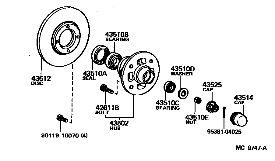
Front Wheel Bearings:
You’ll need the following bearings:
- Inner bearing oil seal (Toyota 43510A) x2
- Inner bearing + race (Toyota 43510B) or (Koyo WB-1012) x2
- Outer bearing + race (Toyota 43510C) or (Koyo WB-1011) x2
Bearings from either Toyota or Koyo should come with the races – but always good to double check.

Other parts:
- Hub grease caps x2
Technically these can be re-used – depends on how bad in shape they are. - Cotter pins and lock caps
These hold the adjusting nut and outer bearing in place. The cotter pin is perishable. - High-temp hub grease
Not to be confused with lithium grease.
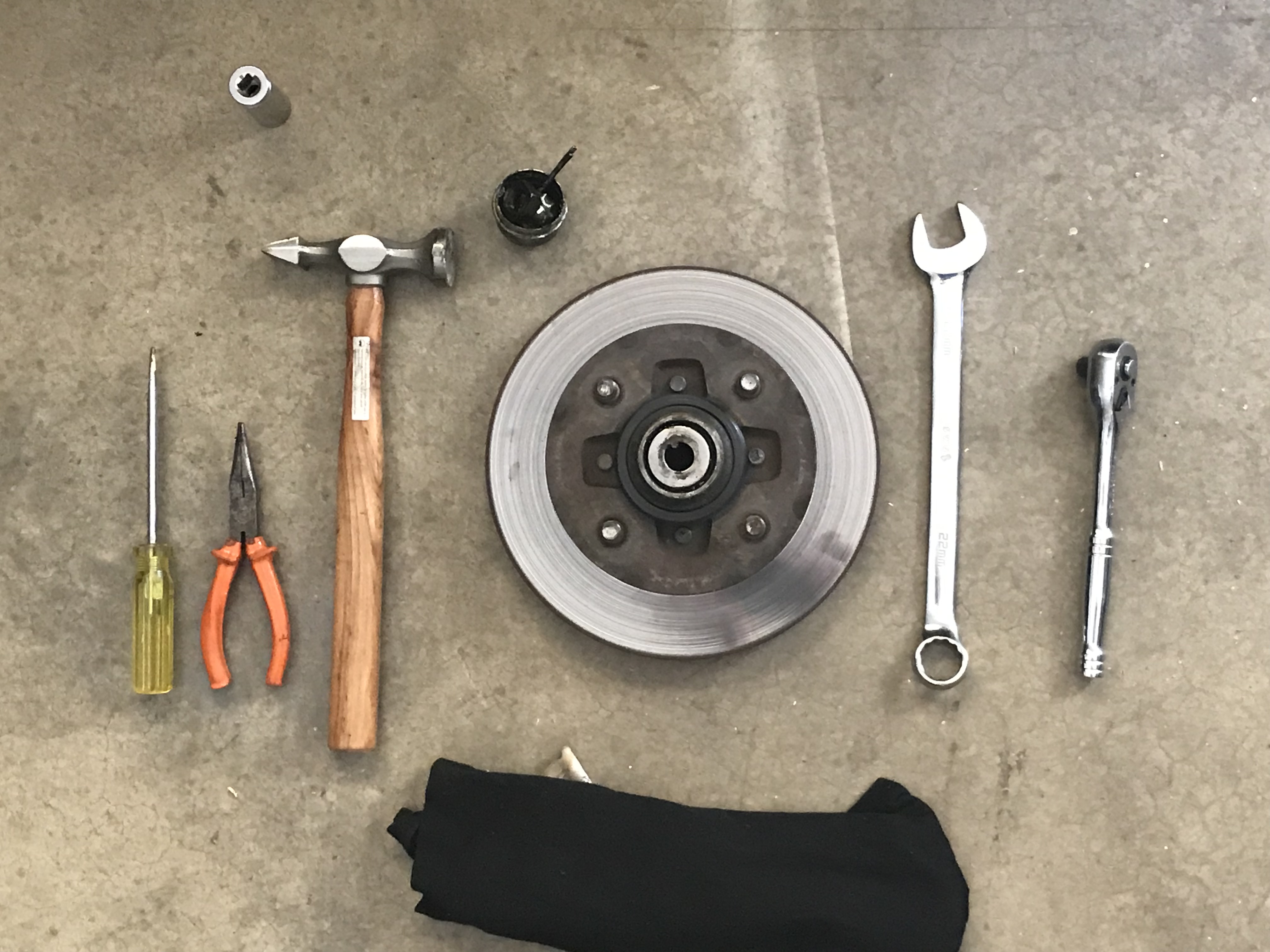
Tools:
In addition to your basic tools/ wrenches:
- Disposable gloves
This is for applying the grease - Flat-head screwdriver or prying bar
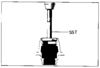
This is to remove oil seals and race seats - Race bearing seating tool SST
This is to properly seat the races, bearings and oil seals
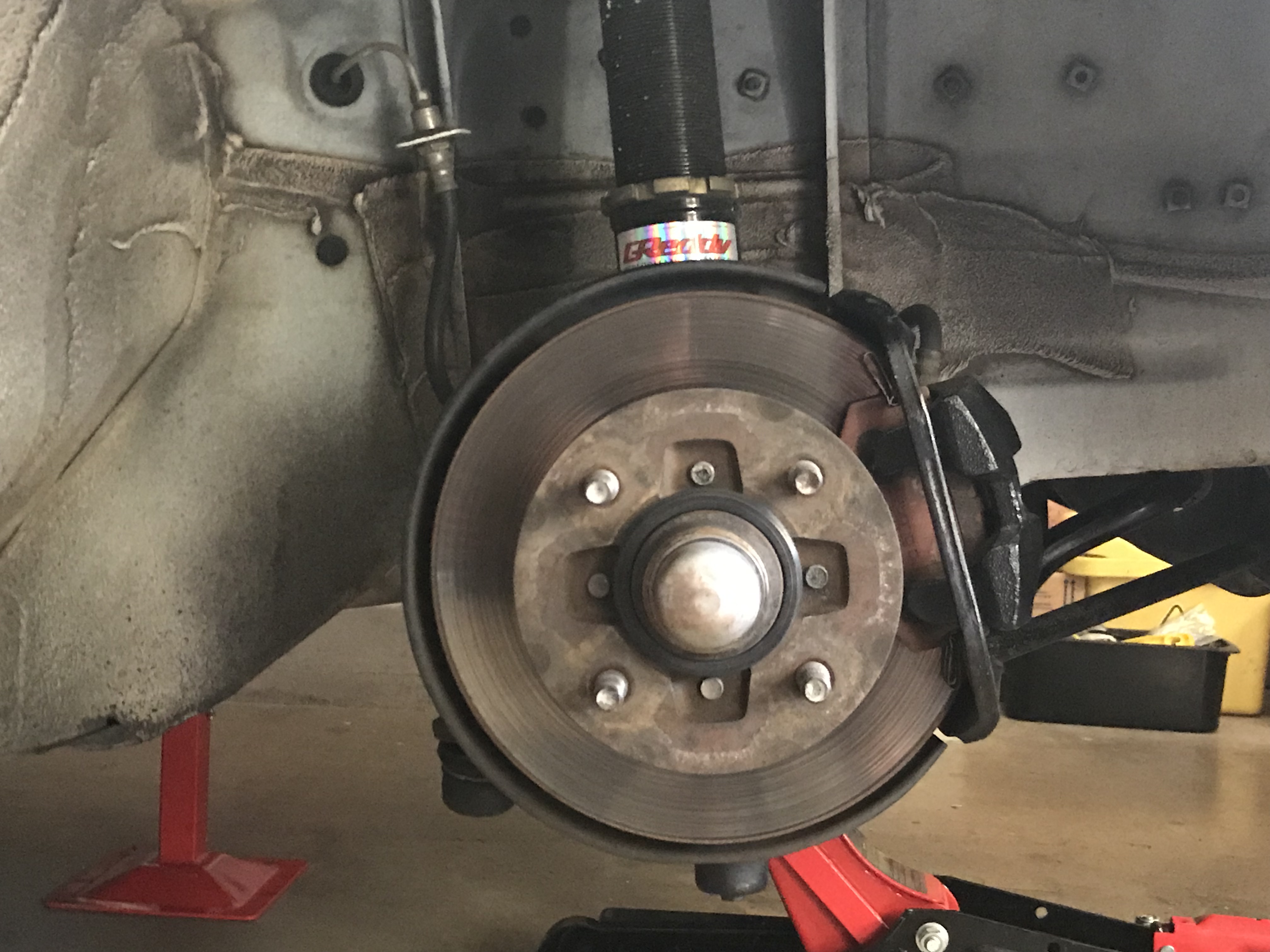
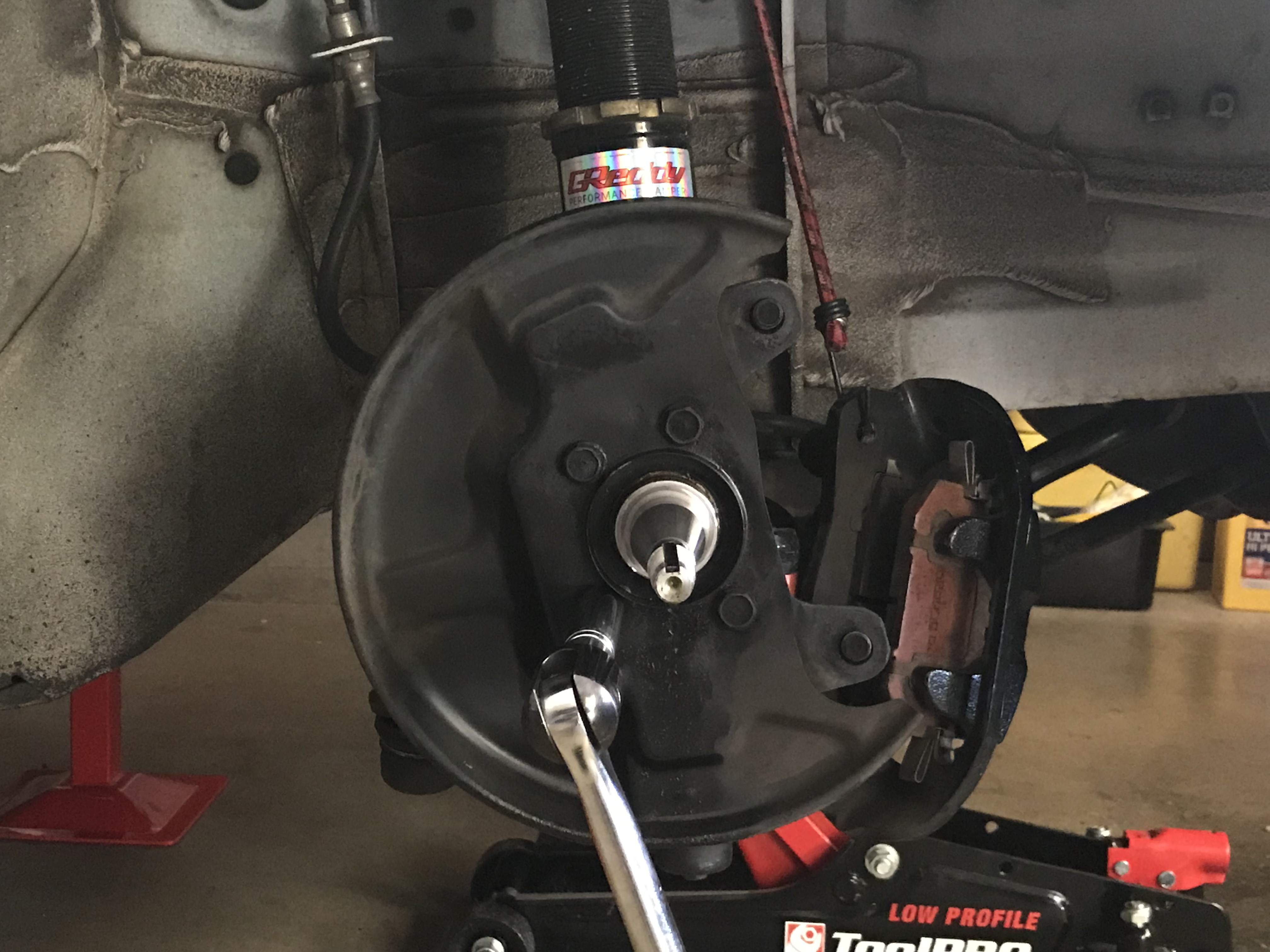
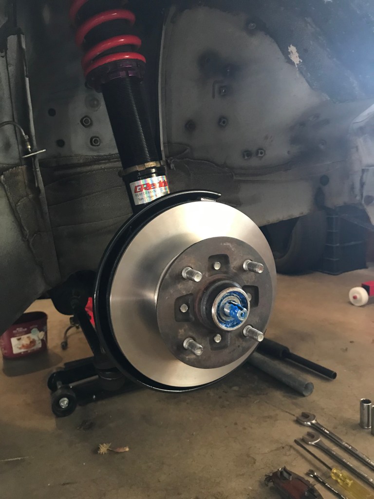
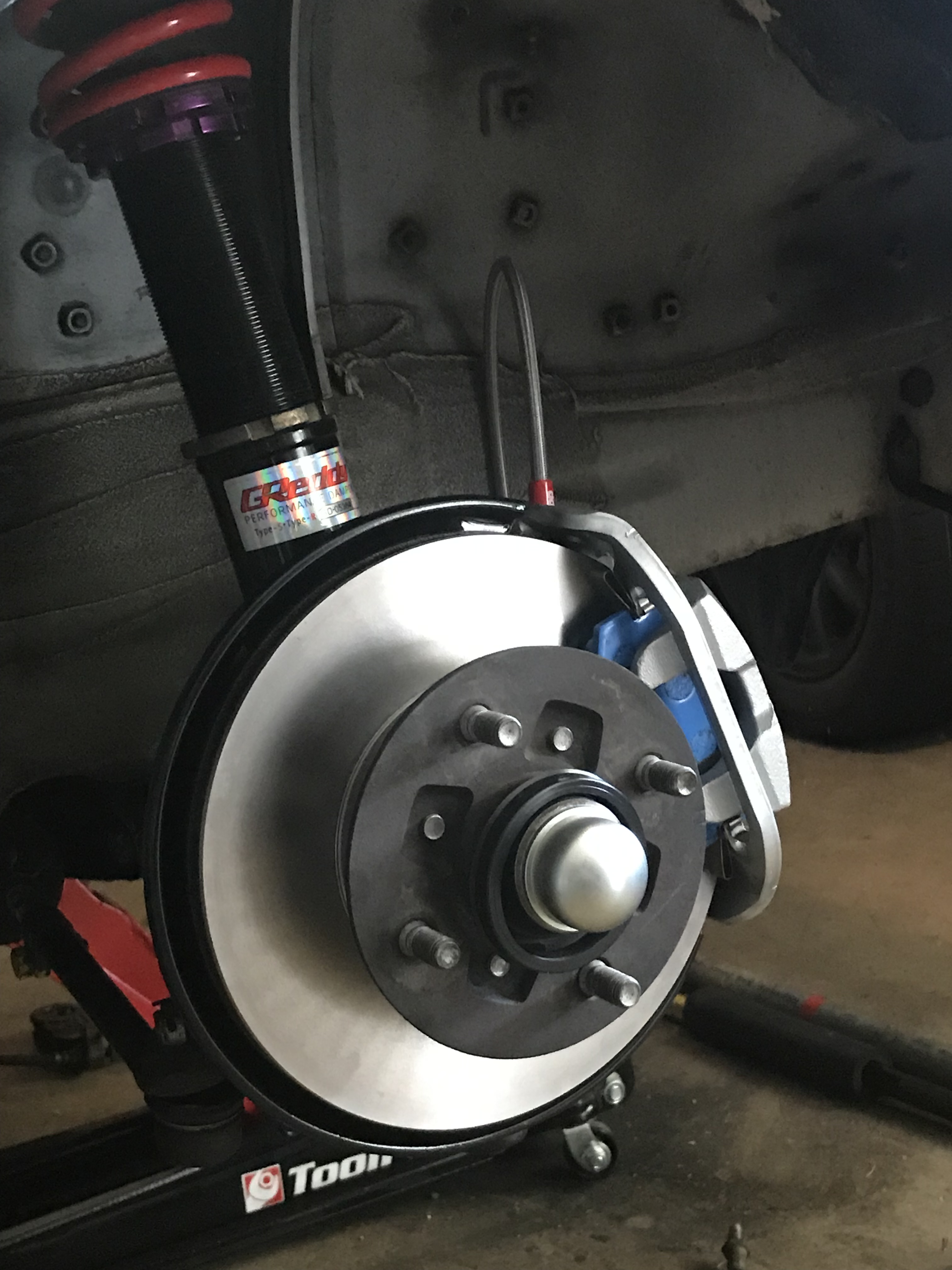
Step 1. Remove hub assembly
- Remove wheels
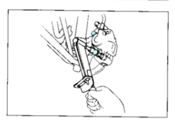
- Remove brake caliper from mounts (47ft-lb)
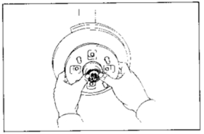
- Remove axle hub grease cap – exposing the cotter pin and lock nut.
- Remove cotter pin, lock nut and adjusting nut.
- Carefully remove hub.
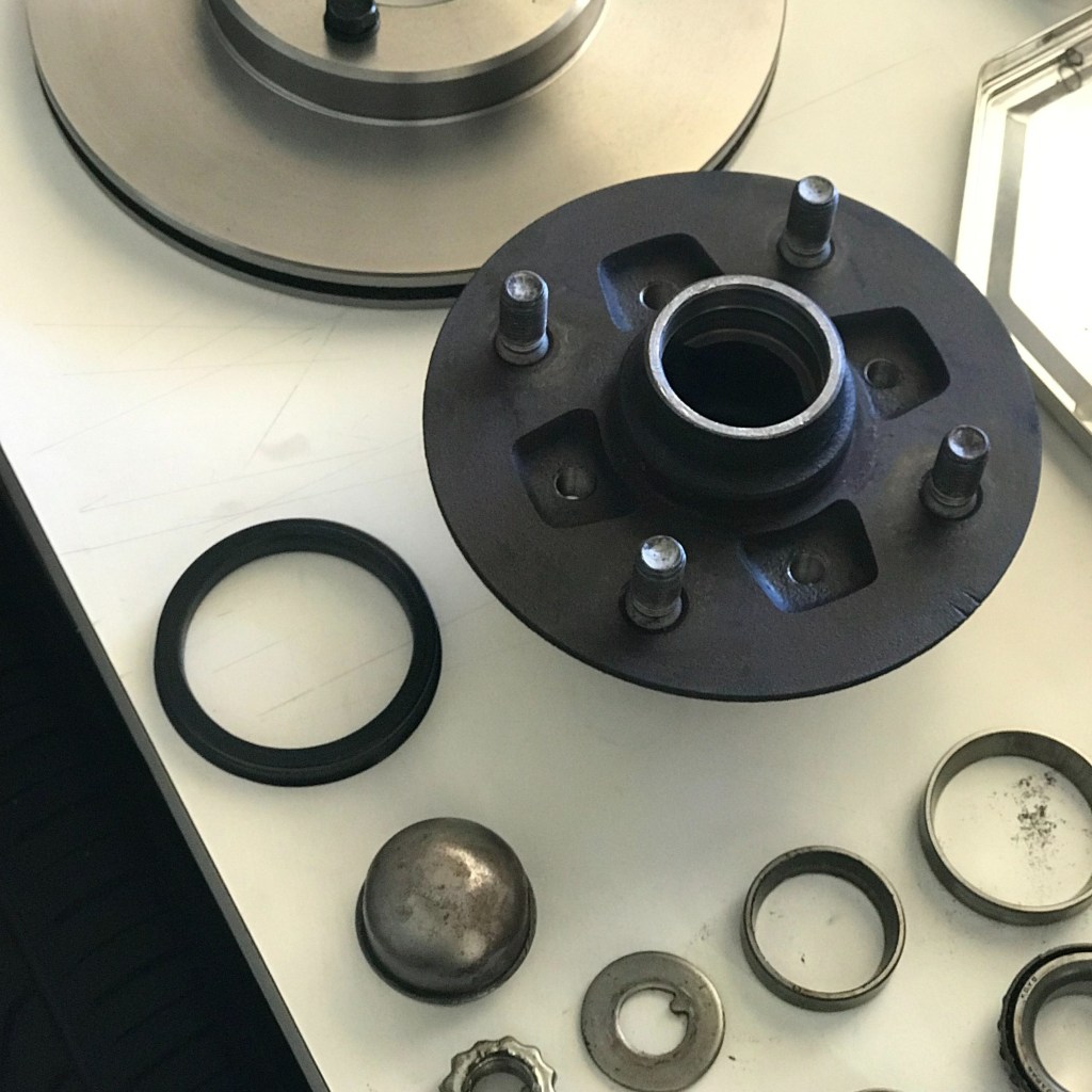
Step 2. Disassemble hub
REMOVE Oil seal & inner bearing
Pry out the oil sea with a screwdriver (some leverage helps). This releases the inner bearing, giving you access to the races:


Remove races from hub
Use a brass or wooden bar to hammer the old outer and inner races out. Brass or wood is soft enough so that you don’t marr the inner walls:
Step 3. Install new components
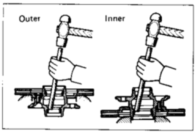
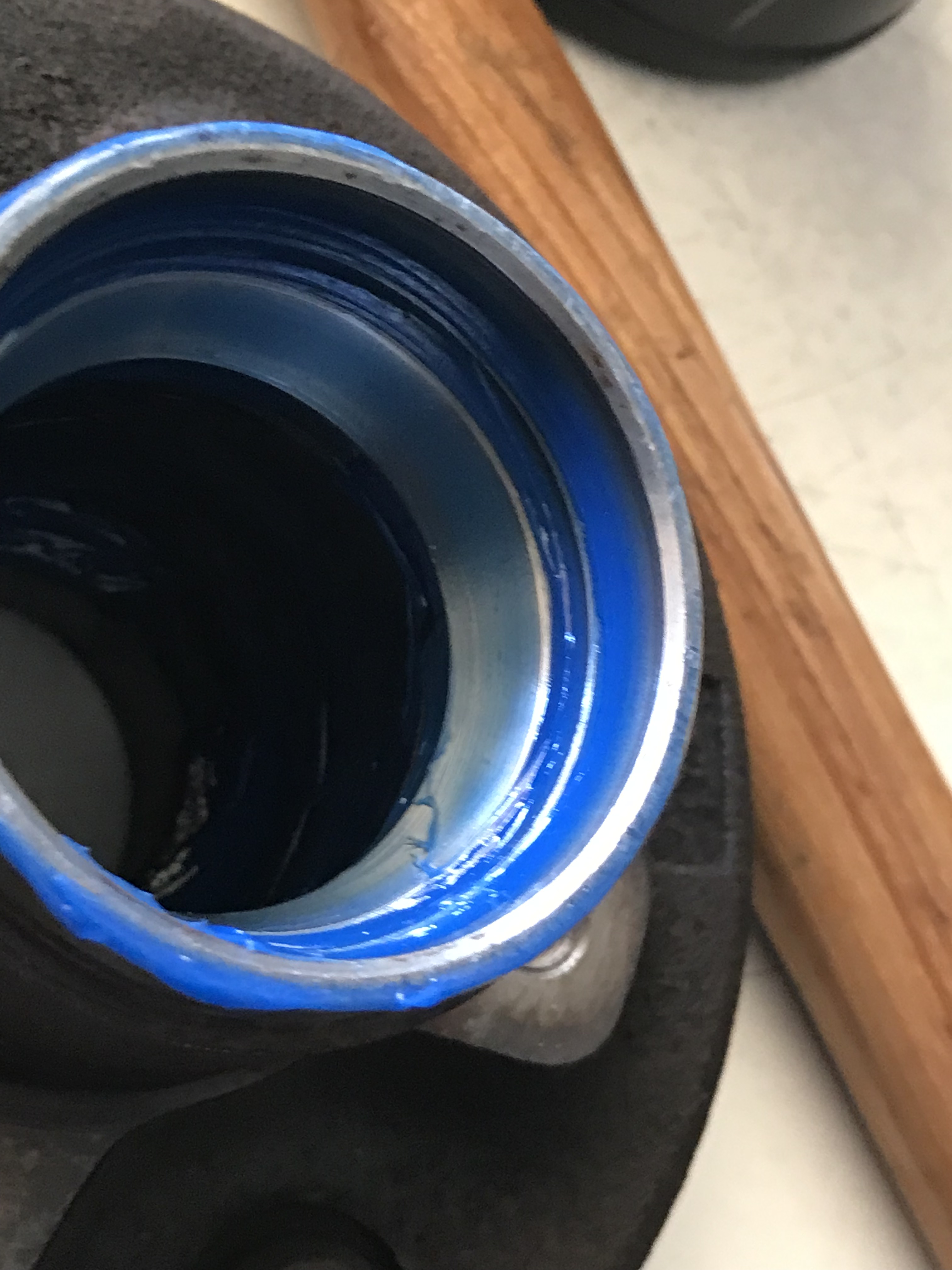
Install New races
Installs the new races into the housing – where the bearings sit and run on.
- Use a SST to drive a new inner and outer race in – grease as required
- Ensure they are seated properly in the hub (that’s what the SST is for)
- Apply grease on the race seats
Note: Outer refers to the smaller race. Inner refers to the larger race.

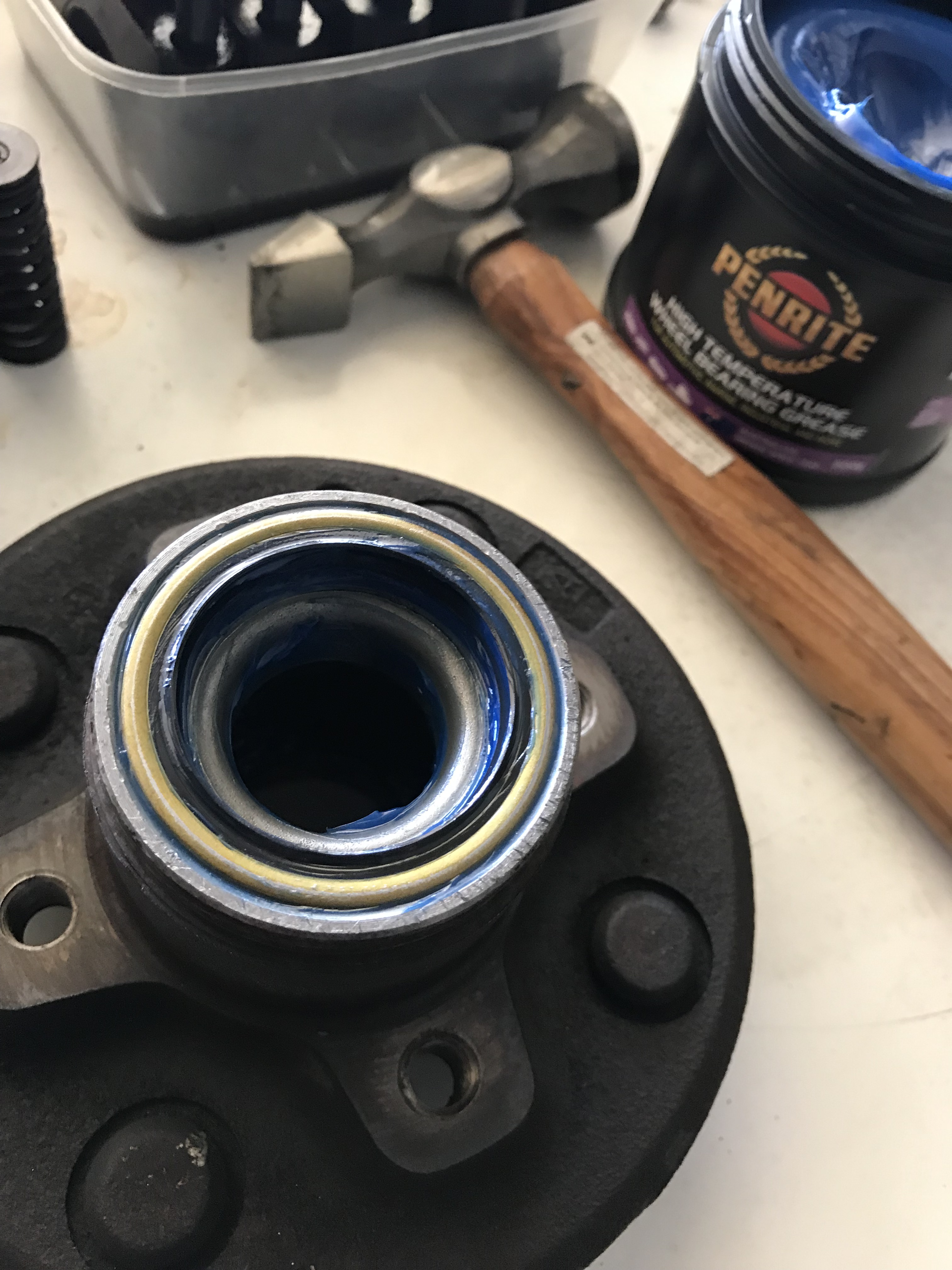
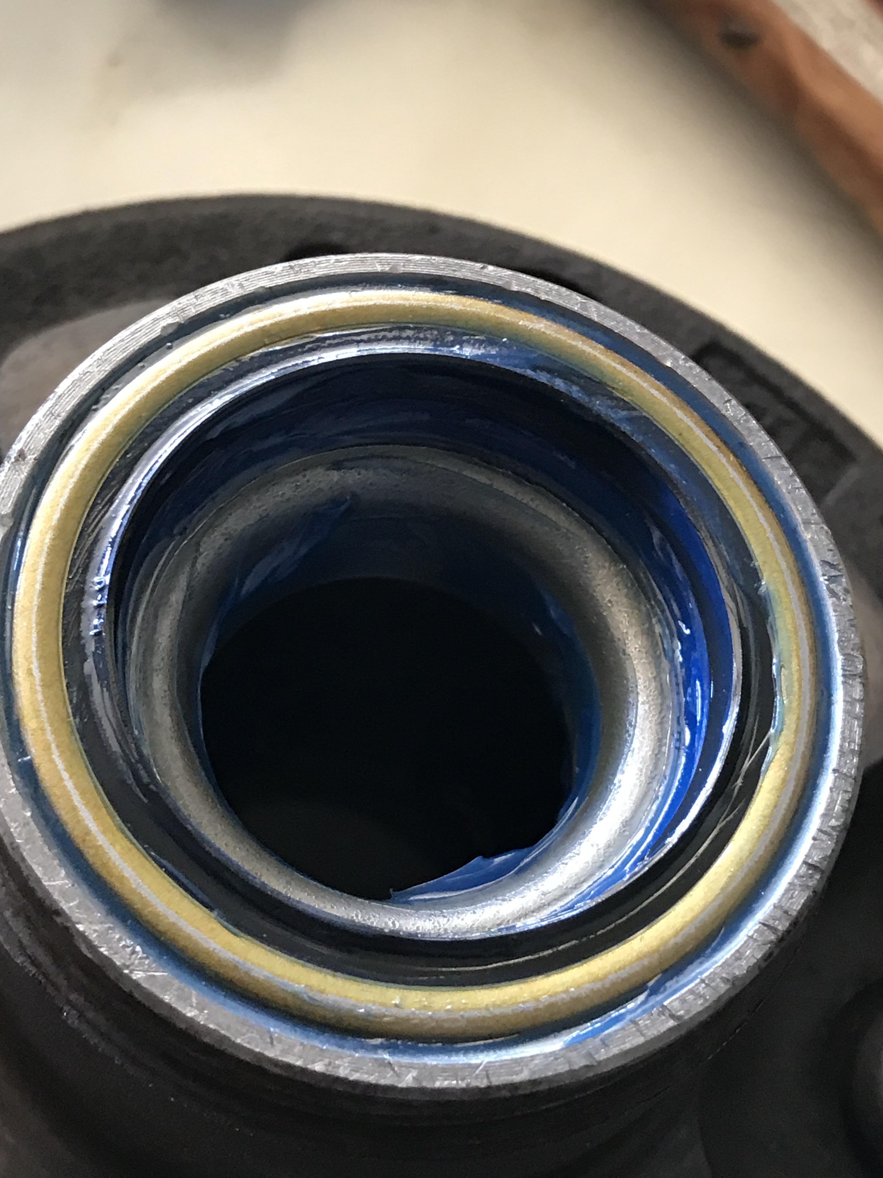
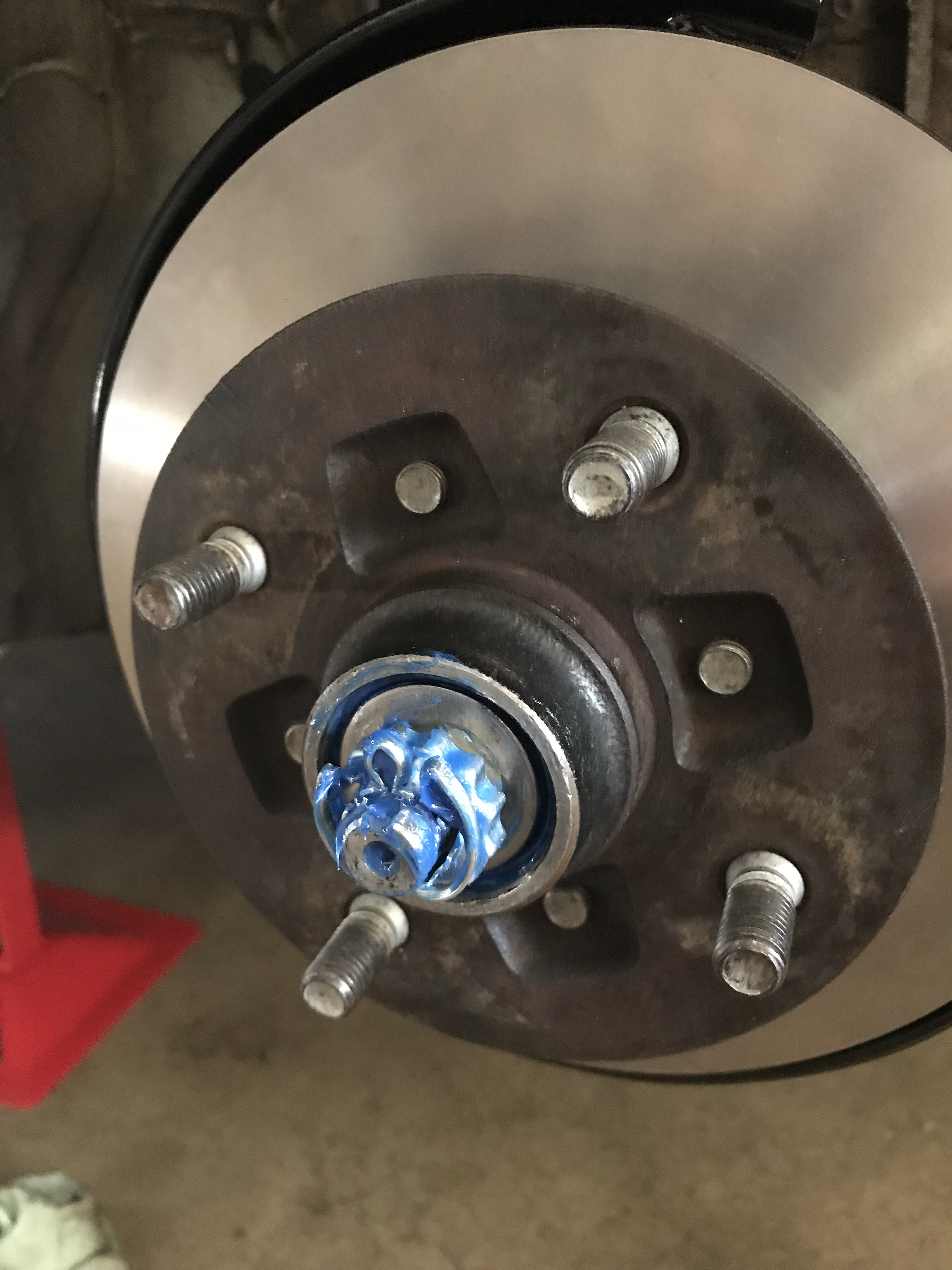
Install NEW inner bearing & oil seal
After the races are driven into place, you can now place the new bearings in.
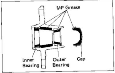
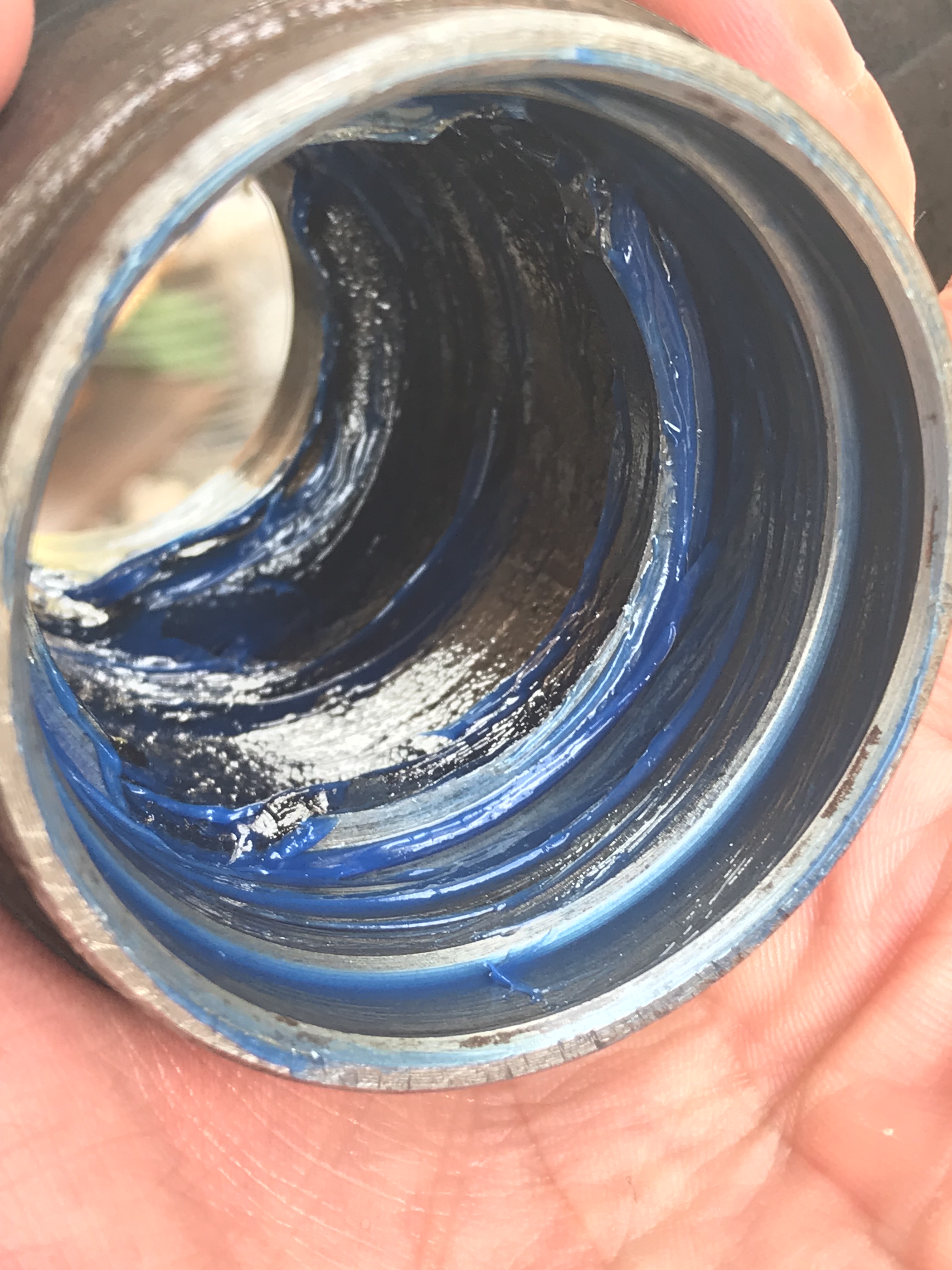
- Pack high-temp hub grease into the inner bearing
- Place bearing into the hub
- Coat the oil seal with grease
- Drive oil seal into the hub with SST – ensure it is seated properly. The curved surface of oil seal is the top. Clasped seal/ lip side is the bottom.


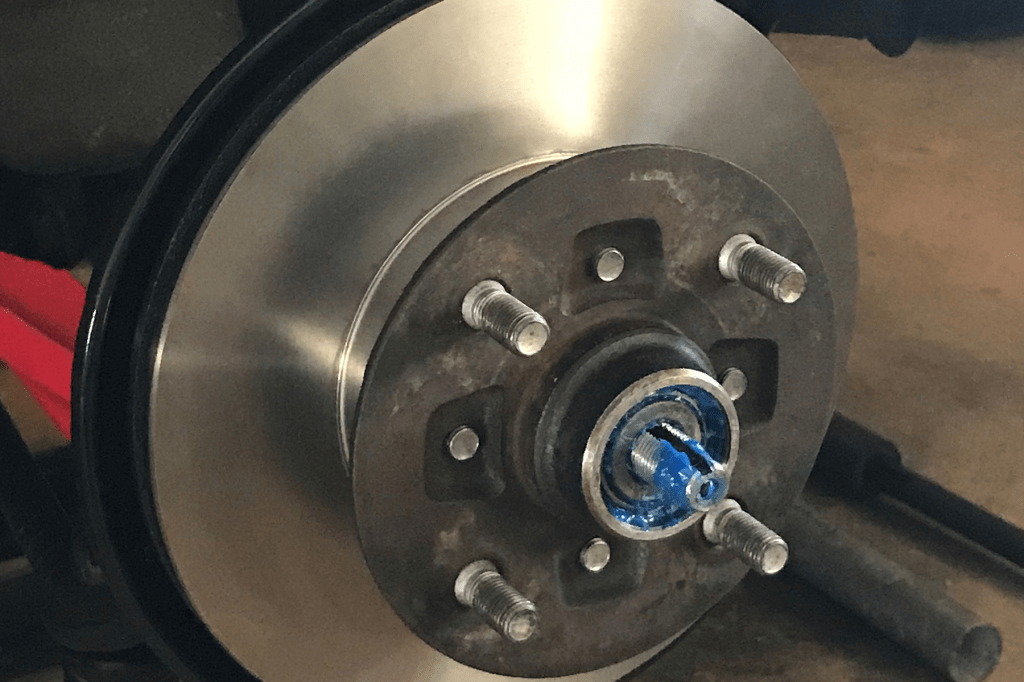
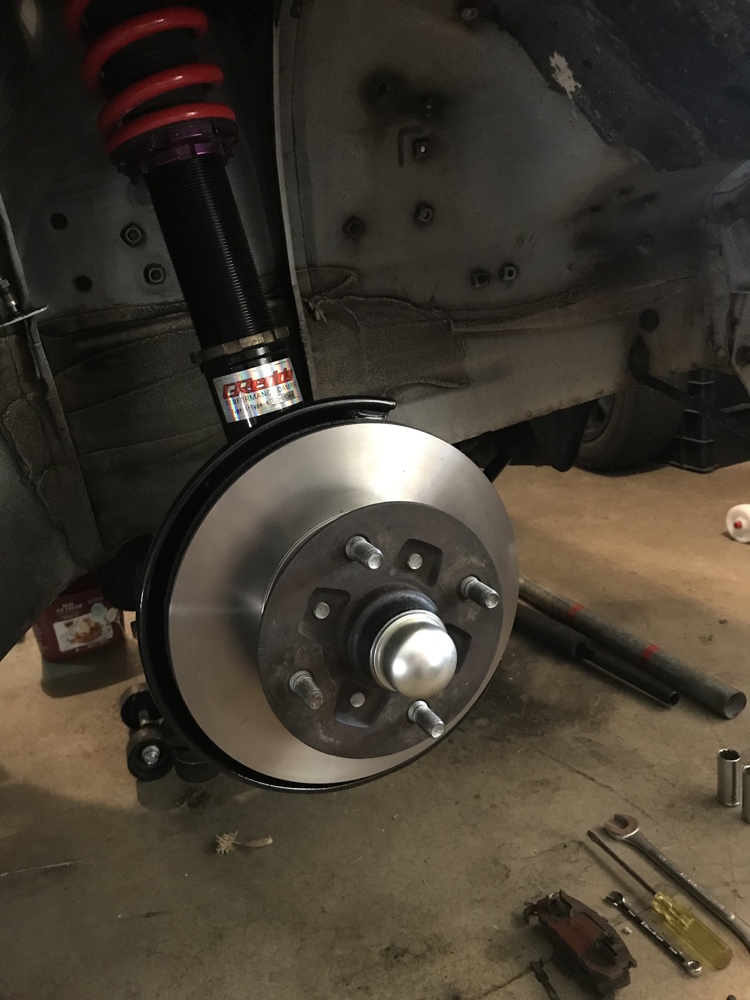
Step 4. Reinstall hub
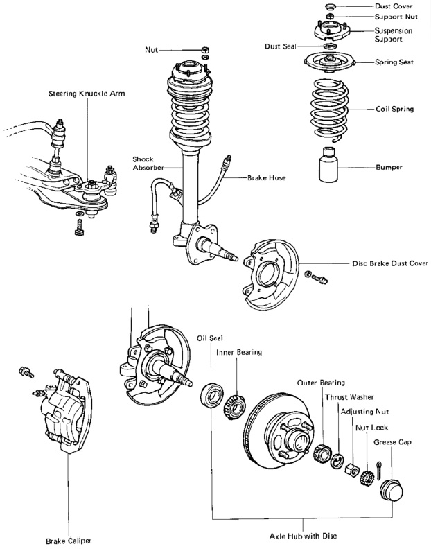
Install axle hub disc assembly to suspension spindle
- Place the hub and disc assembly onto the spindle
- Pack grease into the outer bearing and install it onto the hub
- Install the thrust washer
- Install the adjusting nut
- Preload the adjusting nut to seat the bearings down
Wrench it down by hand or if you need numbers, 21 ft-lb or 290 kg-cm.
Rolling the assembly helps determine if they are seated down properly. - Re-loosen and tighten the adjusting nut by hand again
- Check preload: (should be in the range of 0-1,050g turning effort)
- Once happy, install nut lock to set things in place.
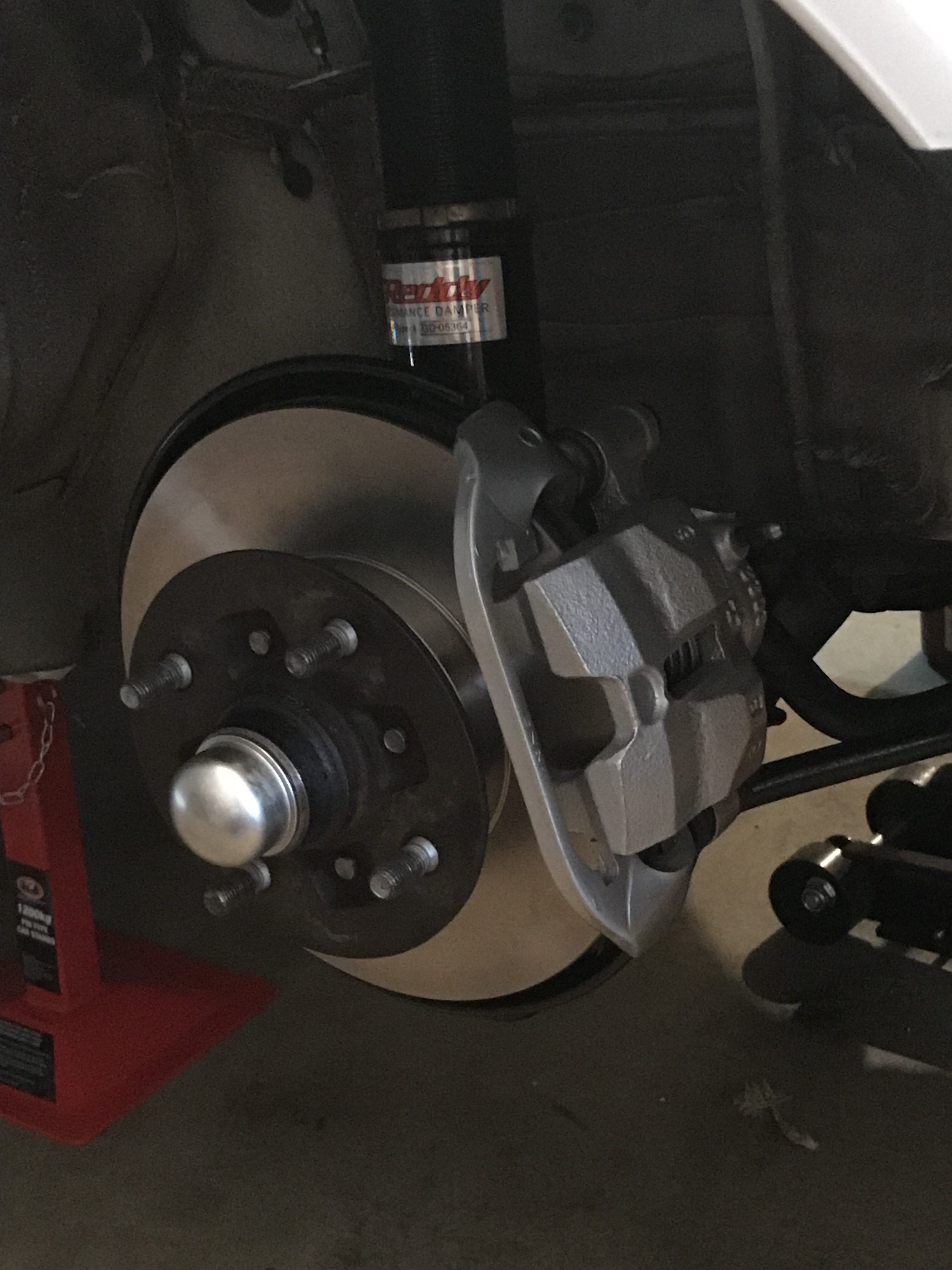
- Install cotter pin and hub cap.The cotter pin prevents the adjusting nut from moving – it ensures the hub can still move freely.
- Re-install brake caliper – mounting bolts = 47 ft-lb or 650 kg-cm.
- Front brake assembly is complete.
- Ensure hub rotates smoothly – re-adjust the nut by hand if required.

Other notes:
Hoses and fittings
If hoses and fittings have been removed, re-install them and hand-tighten them only. After bleeding the brakes, test for leakages and re-tighten by hand as necessary.
Torque specs for fittings
- Brake hose on the caliper specifies: 235kg-cm or 17ft-lb, but hand tightening should be more than enough as you risk over-tightening and caving-in the fittings.
–
Approx 10ft-lb should be enough as the starting point – then tighten as necessary. Over-tightening it will wear it down and you may risk losing any future leeway for tightening remaining.
– - Some Japanese stainless steel hose user manuals specify 10ft-lb – which is significantly less than the Toyota’s manual – Toyota’s torque applies to their rubber hoses with softer fittings in comparison aftermarket ones (aftermarket fittings are strong enough to collapse the caliper fittings).
– - Brake hose to the hard line nut should also be hand-tightened or close to 155kg-cm or 11ft-lb or 15 N-m.
– - Bleeder valve: Also hand-tighten, you basically want to seat the valve flush into the caliper housing so that no fluid can escape into the hole located on the side of the valve. If there’s any dirt where the seats mate, you may introduce enough of a small gap to allow fluid to trickle through:
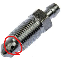
- If you need to replace these, bleeders are 7mm x 1.0 (Japanese spec)
– - Should you need to perform any work on the hard lines, AE86 hard lines should be 3/16″ and the fittings are Toyota metric 10 x 1.0 (M10 x 1.0″ for 3/16″ lines) with double flare SAE / Japanese inverted flare.
– - Inspect and re-tighten as necessary after pressure testing the brakes.
– - Residual fluid sitting inside the bleeder valve is OK – it will just expand as it absorbs air and eventually expel out of the valve. Some mistaken this as a leak, but if you wipe it clean and it’s not there the next day (after normal brake operation), then you’re good to go 🙂
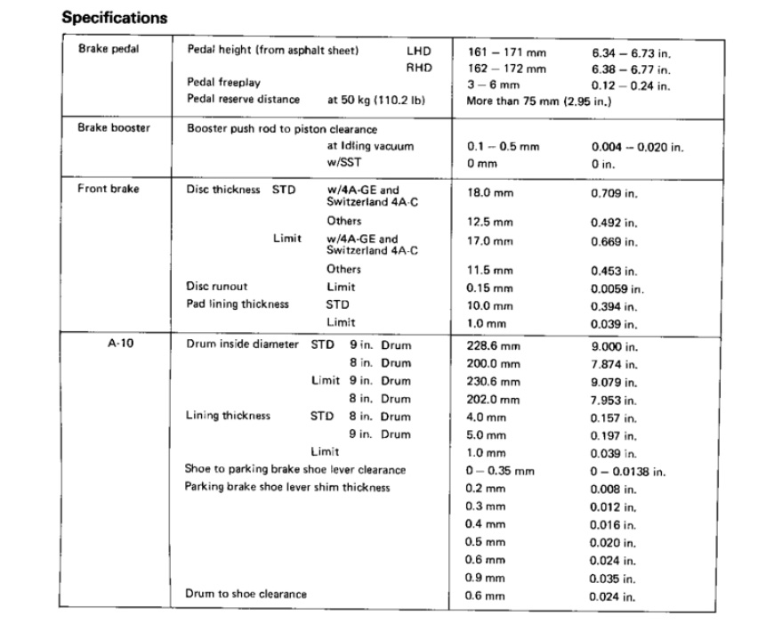
Refer to Tightening Torque part of the screenshot for torque spec related to the hub assembly:

Further references
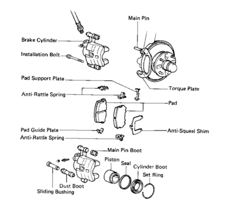
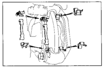
More brake caliper assembly and torque specs:

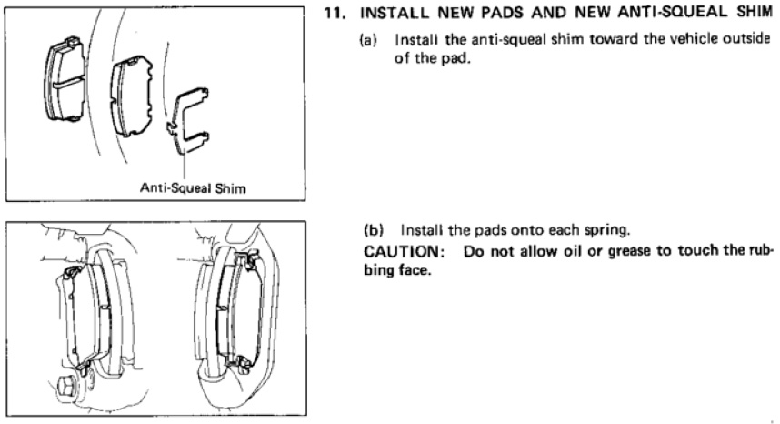
Front caliper brake plates and shims:
Suspension, spindle and hub assembly reference: